HIL test case modeling with CaGe
Test cases developed quickly
The CaGe language is used to model, generate and execute test cases for hardware-in-the-loop test systems. This enables the rapid development of test cases with high test coverage.
miniHIL Test Harness and CaGe
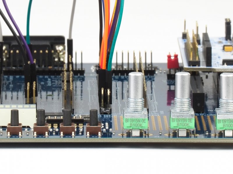
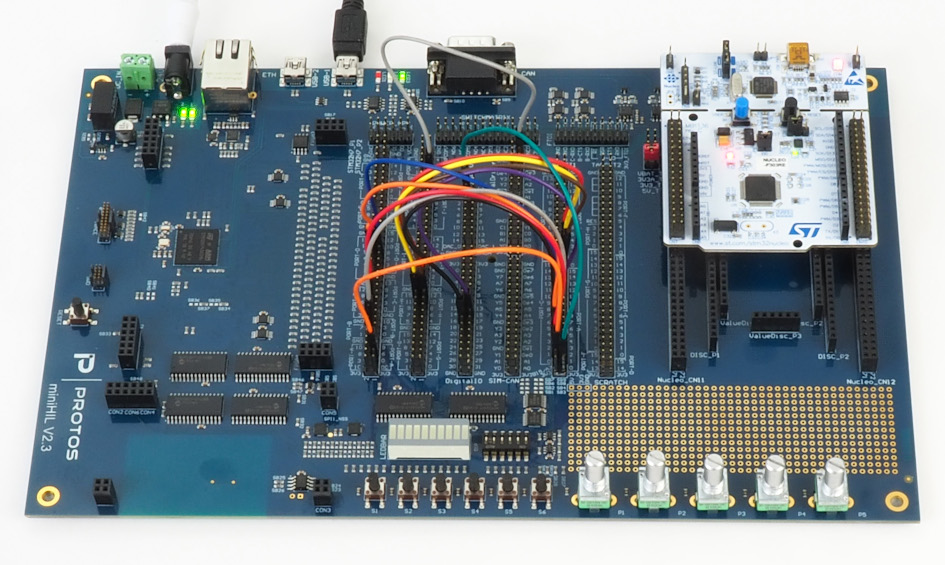
A hardware-in-the-loop test first requires a test harness, which consists of the miniHIL board and the miniHIL simulation environment. This defines the required test environment such as hardware, driver connection of the test system or test interface and ensures that the test setup is reliably reproducible.
CaGe (Case Generator) is the test language of the miniHIL solution, with which the actual test procedure is defined. The test description is done textually in an editor. In addition, the tests are visualized as sequence diagrams, which facilitate understanding and communication of the test cases and serve as documentation.
The following sections present the most important elements of CaGe.
CaGe Step
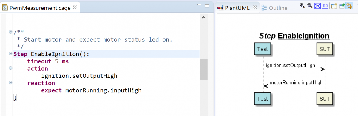
A CaGe Step descrives actions and reactions for the System under Test (SUT). The following example shows a simple test for a motor LED.
The test has two digital pins – one digital output ignition and a digital input motorRunning. First, the test switches on the motor. This is done using the action ignition.setOutputHigh. As a consequence, the SUT should activate the motor LED. The expected reaction is motorRunning.inputHigh.
Note: In the diagram the monitor is assigned to the SUT.
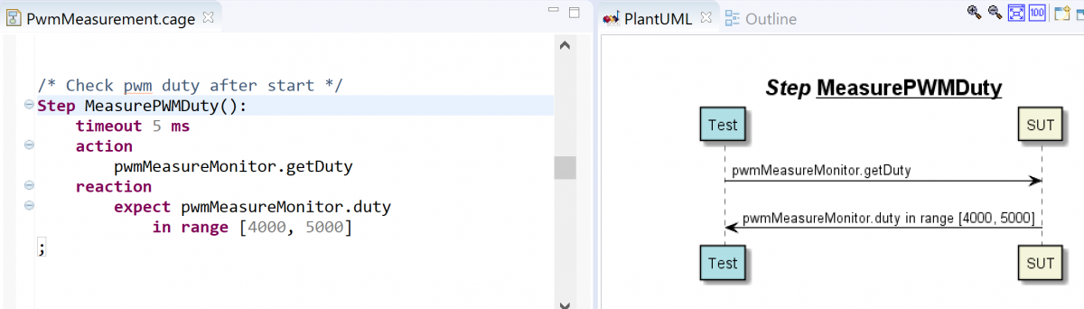
Monitors are part of the miniHIL simulation environment and are not defined in the test language. pwmMeasureMonitor is a concurrent actuator in the test system, which continuously measures the PWM signal of the SUT. Both the hardware connection and the measurement logic are encapsulated in this actuator.
Monitors and Simulations
A CaGe test can use additional monitors and simulations.
The following example sketches the measurement of a PWM signal by means of a monitor called pwmMeasureMonitor. First, the test asks for the current duty cycle of the SUT by invoking pwmMeasureMonitor.getDuty. Then the result value is checked against the expected value (duty in range[...]).
Simulation modules can be used in a test in the same way. They can be used to simulate specific states of the test environment, such as special sensor signals or a cable break, as well as to create complete environment simulations. Examples are simulations of motors, batteries and residual bus simulations.
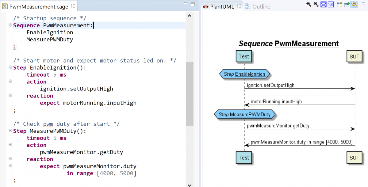
CaGe sequence
A CaGe sequence calls other CaGe steps and sequences. In this way it is possible to reuse test logic or create higher level test sequences.
In the following screenshot the sequence PwmMeasurement is depicted, which combines the steps EnableIgnition and MeasurePwmDuty.
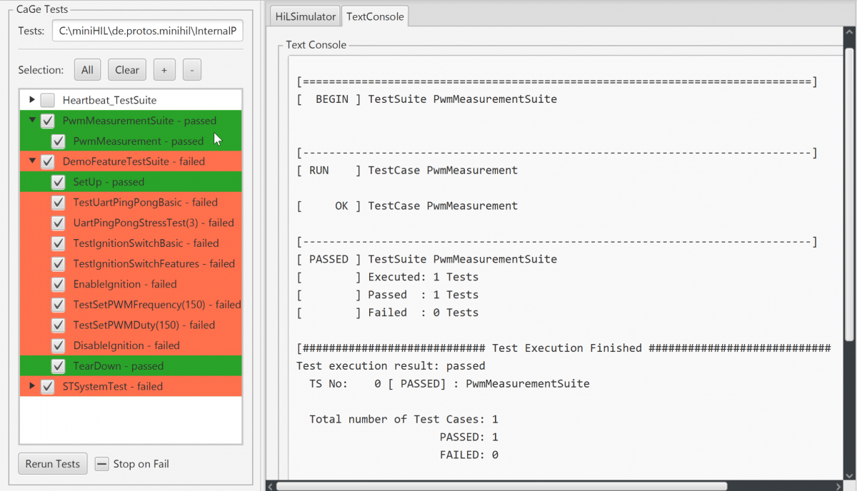
Test execution
When the miniHIL board is connected to the PC, tests can be conveniently run from the command line or a graphical user interface (GUI). Below is a screenshot of the GUI. On the left side is the control panel for test selection and execution. Textual logging is displayed on the right side.
Test logging
A CaGe test is recorded at runtime. Thus, the test sequence including action and reaction of the SUT is transmitted to the PC and visualized as a sequence diagram. In the following diagram, three diagrams can be seen. The first is the expected test sequence available during test development and already shown in the previous sections. The remaining two diagrams each show an actual test flow as recorded at runtime. The middle diagram is a successful test run, the right diagram is a failed test run.
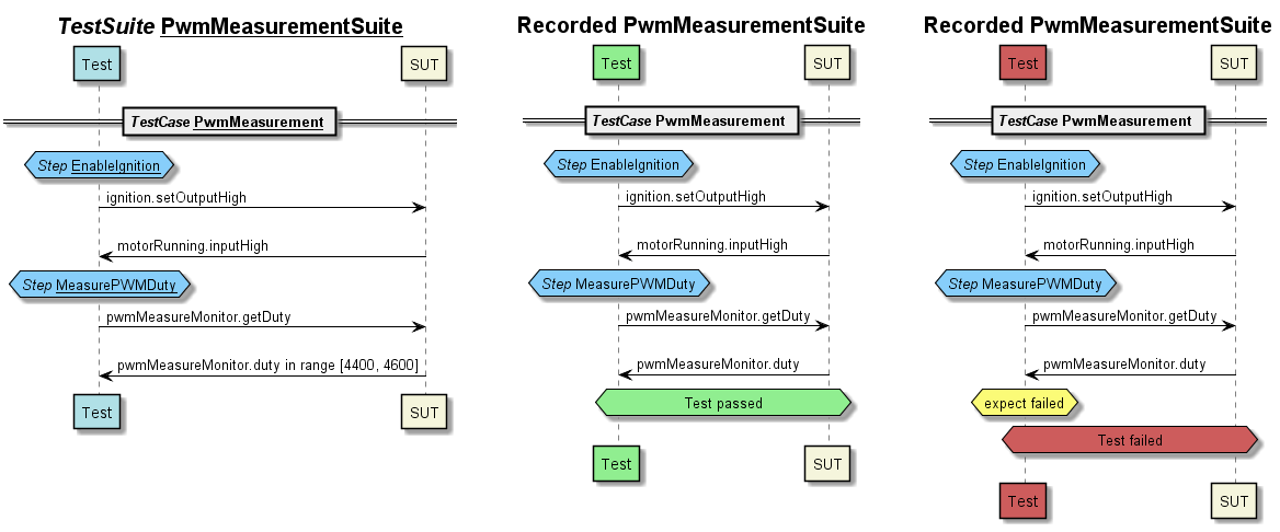
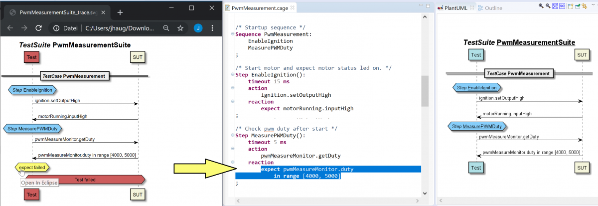
The diagrams contain links that refer to the test definition. For example, clicking on "expect failed" of the failed test run leads to the statement in the editor which was responsible for the error.
The whole sequence or the three steps on their own can now be called in the test. It is also possible to swap them out into a library so that they are available for other test projects. This way, a reusable test library can be created.
Test parameters
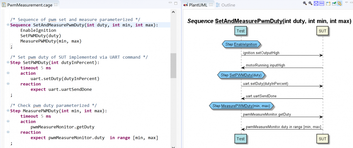
CaGe sequences can be parameterized so that they become reusable. This allows testing with different sets of parameters.
The following example shows a parameterized sequence. This calls 3 steps one after the other: EnableIginition, SetPWMDuty and MeasurePWMDuty.
The step SetPWMDuty takes a parameter which is used to specify the expected value for the PWM-signal of the SUT. The step MeasurePWMDuty takes a minimum and a maximum value for the measurement of the expected signals.
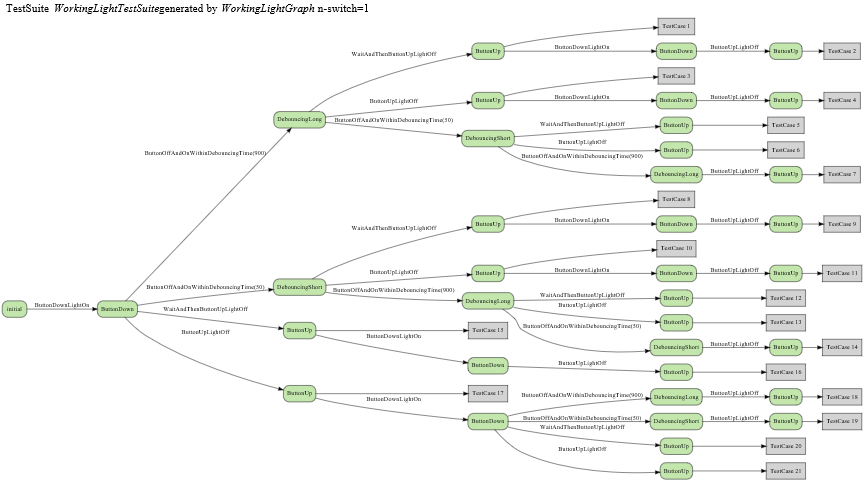
CaGe is able to generate concrete test cases from the paths of the graph. The diagram below shows the result of a test case generation with the so-called n-switch method, which in this case is n=1 and leads to 21 test cases.
Combinatorial test case generation
A special feature of CaGe is the creation of combinatorial tests, from which test cases are generated (State Transition Testing). State Transition Testing is a technique from the field of Model Based Testing (MBT).
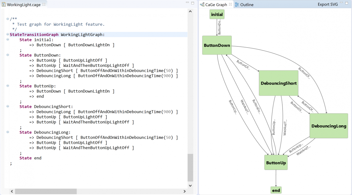
In the previous examples, the test flow was realized by sequences. Alternatively, the test sequence can be modeled by a State Transition Graph. The graph allows defining a sequence, which can consist of any number of repetitions or different combinations of sequences. The following screenshot shows a graph that contains several back transitions and cycles. Each path through the graph is a possible test case.
Test case generation can be used to significantly increase test coverage. In addition, errors that are otherwise difficult to find, such as race conditions or deadlocks, can be uncovered in this way.
The blog post kombinatorial state transition tests for embedded systems is also available on this topic.

Test case modeling with CaGe provides:
- Textual language for test definition (suitable for GIT/SVN).
- Graphical visualization of tests
- Use of complex monitors and simulations
- Test execution via graphical user interface or from the command line
- Recording of the test sequence at runtime
- Combinatorial test case generation
- Automated test execution (Continuous Integration)